

 axial glass thermistor")


Among other things, the battery management system (BMS) must closely monitor the voltage, current, and temperature of the battery and battery pack. Temperature measurement is very important to ensure the normal operation of the battery and BMS, as well as to prevent the degradation of performance, especially during fast charge and discharge.
Temperature measurement typically reads the voltage of a device that changes with temperature—in most cases, it is a resistive device, such as a thermistor or a resistance temperature detector (RTD). Other technologies such as thermocouples require cold junction compensation and proper shielding of millivolt readings, while diode / BJT-based temperature sensors require constant current excitation. The main advantages of using NTC thermistors are high sensitivity, excellent accuracy, cost-effectiveness, and strong versatility. This type of device has the characteristics of convenient contact measurement and is the best temperature sensing option for monitoring each point or surface. See Table 1 for comparison of different contact temperature measurement technologies. Thermocouples are often used during the design phase.
In high power battery packs, because the size of the battery pack and the internal thermal gradient of the battery pack are determined by a single battery and / or charge and discharge conditions, the BMS requires multiple temperature sensor inputs to ensure the best overall performance.
The negative temperature coefficient (NTC thermistor) exhibits a resistance / temperature nonlinear exponential drop, as shown in Figure 1 and Equations 1 and 2.
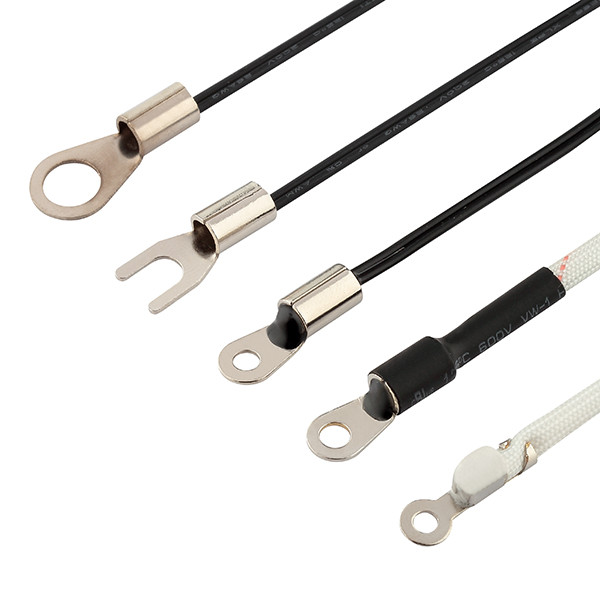
The advantage of NTC thermistors is that they can generate different resistance values (R25) and slopes (B values) in many different ways, from (external) PCB surface mounting, screw-mounted highly insulated surface sensors, and even soldering to terminal posts on.
As shown in Figure 2a, when used in a resistor divider network, the thermistor voltage changes in an S shape with temperature (see Figure 2b and Equation 3).
In Figure 2b, the relationship between temperature and Vtherm can be established through a look-up table (LUT) or using the algorithm (2) + (3). In this way, the ADC and controller IC can apply predefined policies to control different charging stages of the battery pack or health status.
As a simple example, we can use LTC4071 from Analog Devices, a lithium-ion and lithium polymer battery charger IC for energy harvesting and embedded automotive systems.
The simulation is shown in Figure 3. The schematic basically duplicates the SPICE macro model and lithium-ion battery model of Analog Devices’ LTC4071.
The graph in Figure 4 represents the simulation results (simplified). Lithium-ion batteries begin to charge under three different voltage conditions (controlled by IC): 4.2 V full charge; 3.6 V 50% charge; 3.0 V empty). At the beginning (time 0), the battery ambient temperature was 20 ° C, gradually increased to 70 ° C, and then returned to normal ambient temperature. To ensure long-term stability, battery packs used in electric vehicles (EVs) typically operate in the range of 20% to 85% of power, so they are rarely charged at 4.2V full-voltage or below 3.2 V battery voltage Discharge.
Figure 4 shows the behavior of the BMS when the temperature reaches different critical thresholds.
As the temperature (represented by the voltage source V1) rises, the thermistor changes accordingly, and the delay is determined by the system response time. The initial voltage is 4.2 V (green curve). When the temperature reaches different continuous rising thresholds, it will be discharged for a short time, and the battery voltage will gradually decrease gradually. The initial voltage is 3.0 V (red curve). Charging stops when the rising temperature reaches the first threshold, and restarts charging when the temperature falls below a certain level.
To achieve the best accuracy and repeatability of battery temperature measurements, Vishay offers a variety of NTC thermistors. NTCALUG01T has a service life of up to 10,000 hours at 150 ° C, and the high-voltage / power connection terminals and terminals have a temperature resistance of 2.7 kV, which is different from the voltage level of the controller circuit. Another option for temperature sensing on metal surfaces is the NTCALUG02 thermistor, which has a thermal gradient of less than 0.05 K / K.
In electric vehicles / hybrid vehicles, BMS can use different temperature sensing strategies, which mainly depend on battery characteristics, assembly design, and control IC algorithms. This in itself is a complete hybrid discipline and is evolving. In this hot area, as a device manufacturer, Vishay makes its own contribution by developing a variety of mechanical actuators and electrical simulation models, and will continue to promote technological development in this area in the future.
 axial glass thermistor")


