

 axial glass thermistor")


1.Function and type of temperature sensor
Temperature is an important parameter that reflects the state of the engine’s thermal load. In order to ensure that the control system can accurately control the operating parameters of the engine, the engine coolant temperature, intake air temperature and exhaust temperature must be monitored at any time in order to correct the control parameters, calculate the mass flow rate of the intake cylinder air and perform exhaust gas purification treatment.
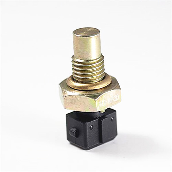
The Coolant Temperature Sensor (CTS) is commonly referred to as a water temperature sensor and is mounted on the engine coolant outlet pipe. Its function is to detect the temperature of the engine coolant and convert the temperature signal into an electrical signal for transmission to the ECu. The ECU corrects the injection time and the ignition timing based on the temperature signal of the engine, so that the engine operating conditions are optimally operated.
The Intake Air Temperature Sensor (IATS) is installed in the intake line. Its function is to detect the intake air temperature and convert the temperature signal into an electrical signal for transmission to the ECU. The intake air temperature signal is a correction signal for various control functions. If the intake air temperature sensor signal is interrupted, it will cause difficulty in hot start and increase in exhaust gas emissions.
It is well known that air weight is related to intake air temperature and atmospheric (intake) pressure. When the intake air temperature is low, the air density is high, and the weight of the same volume of gas is increased; conversely, when the intake air temperature is increased, the weight of the same volume of gas is decreased. In a fuel injection system using a manifold pressure type, a vane type, a Kalman vortex type, and a core air flow sensor, since the air flow rate measured by the air flow sensor is a volume flow rate, an intake air temperature sensor and an atmosphere are required. Pressure Sensor. The ECU corrects the fuel injection amount based on the intake air temperature and pressure signal of the engine, so that the engine automatically adapts to changes in external ambient temperature (cold, high temperature) and pressure (plateau, plain). When the intake air temperature is low (high air density), the resistance value of the thermistor is large, the signal voltage of the sensor input ECU is high, and the ECU controls the injector to increase the fuel injection amount; otherwise, when the intake air temperature is high (the air density is low) ), the thermistor resistance is small, the signal voltage of the sensor input ECU is low, and the ECU will control the injector to reduce the fuel injection amount.
There are many types of temperature sensors, such as thermistor type, metal thermistor type, wirewound resistor type, and transistor type. The thermistor can be divided into a Positive Temperature Coefficient (PTC) type thermistor, a Negative Temperature Coefficient (NTC) type thermistor, a Critical Temperature Resistor (CTR), and Linear thermistor. Commonly used thermistors are negative temperature coefficient type and positive temperature coefficient type. NTC type thermistor temperature sensors, such as coolant temperature sensor (CTS), intake air temperature sensor (IATS), Ex-haust Air Temperature Sensor (EATS), fuel temperature sensor (FuelTemperature Sensor) , FTs) and so on.
2. Several common temperature sensors
1.Wirewound resistance temperature sensor
It is made by winding a high-purity nickel wire on an insulated bobbin and then covering it with a suitable jacket for measuring the cooling water temperature and the intake air temperature. Use characteristics whose resistance value changes with temperature. The accuracy is within ±1%, the response characteristics are poor, and the response time is about 15s. It is not commonly used now, so it will not be described in detail in this book.
2. Thermistor temperature sensor
(1) Structure and type of thermistor type temperature sensor
The actual structure of the thermistor temperature sensor is shown in Figure 2-2. Its structure is shown in Figure 2-3. It is mainly composed of a thermal element, a metal lead, a terminal block and a housing.
Threads are made on the housing of the sensor for installation and removal. The terminal blocks are divided into single-terminal type and two-terminal type. The fuel injection system of medium and high-grade cars generally adopts two-terminal temperature sensor. The low-speed car fuel injection system and automobile instrument generally adopt single-terminal temperature sensor. If there is only one terminal on the sensor socket, the housing is an electrode of the sensor. At present, most of the temperature sensor sockets used in the electronic control system have two terminals, which are respectively connected with corresponding terminals on the ECU socket to reliably transmit signals.
The main component of the thermistor type temperature sensor is a heat-sensitive element, and the shape is made into a pearl shape, a disc shape (pill shape), a washer shape, a chip shape, a thick film shape, and the like, and is placed in a metal tube case of the sensor. An electrode is drawn from each of the two end faces of the thermosensitive element and connected to the sensor socket. The materials for making thermistors are classified into low temperature, medium temperature and high temperature. The materials for the thermistors for low-temperature measurement are MnO-NiO series, MnO-CoO-NiO series and MnO-CoN series, etc. These are all N-type ceramic semiconductor materials of metal oxide series, which are in the field of measurement and temperature compensation. A wide range of uses. In the engine control system, they are mainly used for sensors for low temperature measurement such as water temperature sensor and intake air temperature sensor, that is, for measuring sensors of 300% or less. Medium temperature measurement materials are SiC, LaCrO3, B4C series, but this
These materials are difficult to sinter and it is difficult to form a mass-produced and inexpensive product. The material of the thermistor for high temperature measurement is ZrO2, TiO2, Y2O3, CaSiO3, Al2O3, Cr2O3, etc., wherein the melting point of ZrO2 is as high as 2800 ° C, and the heat resistance is very good, and the practical proof is the best material for manufacturing high temperature sensor.
(2) Principle and characteristics of thermistor temperature sensor
The thermistor is made by utilizing the characteristic that the resistance value of the ceramic semiconductor material changes with temperature, and the outstanding advantages are high sensitivity, good response characteristics, simple structure, and low cost. NTC thermistors are commonly used in coolant temperature sensors and intake air temperature sensors in automobiles. The relationship between resistance and temperature can be expressed by the following formula:
The constant B value of the thermistor for low temperature measurement ranges from 2,000 to 10,000 K, and the usual value is about 3000 K. The constant B value of the thermistor for high temperature measurement ranges from 10,000 to 15,000K.
For a certain structure of NTc thermistor temperature sensor, the relationship between resistance and temperature can be obtained from equation (2-1) as shown in Figure 2-4. It can be seen that the NTC thermistor has the characteristics of decreasing temperature resistance, increasing temperature resistance, and exhibiting a significant nonlinear relationship. The working circuit of the temperature sensor is shown in Figure 2-5. The two electrodes of the sensor are connected to the ECU socket by wires. The ECU is internally connected with a voltage divider resistor. The ECU provides a stable voltage (typically 5V) to the voltage divider circuit composed of the thermistor and the voltage divider resistor. The signal voltage input to the sensor is equal to the voltage divider value of the thermistor.
When the temperature of the measured object increases, the resistance value of the sensor decreases, and the voltage dividing value on the thermistor decreases. Conversely, when the temperature of the measured object decreases, the resistance of the sensor increases, and the partial pressure on the thermistor The value rises. Based on the received signal voltage value, the ECU can calculate the corresponding temperature value for real-time control.
3. Thermal ferrite temperature sensor
(1) The structural thermistor ferrite temperature sensor is composed of a casing, a ferrite, a reed switch, and a permanent magnet. Two annular ferrites and permanent magnets are arranged in the electromagnetic circuit of the reed switch. The reed switch is turned on or off by utilizing the characteristic that the ferrite magnetism changes abruptly with temperature. Such sensors are generally used to control electric fans and oil pressure indicators of automobile radiators.
(2) Working principle
The thermosensitive ferrite is a ferromagnetic material. When the temperature exceeds a certain temperature, the magnetic permeability of the ferrite sharply decreases, that is, the property of rapidly changing from a ferromagnetic body to a normal magnetic body (weak magnetic body), such a sharp change temperature It is called the Curie temperature. With the Curie feature, the reed switch can be turned on or off.
Different Curie temperatures can be obtained by selecting different sintering material components and heat treatment methods as needed. For example, to control the engine cooling water temperature to be maintained between 65 and 100%: When the Curie temperatures of the two ferrites are 100 ° C and 65 ° C, respectively, the magnetic field strength corresponding to the temperature range becomes as shown in Figure 2-6. The magnetic flux ring shown.
When the ambient temperature of the thermite ferrite is lower than 65 ° C, the two ferrites are ferromagnetic, magnetized by the permanent magnets, and form a magnet with them, and the flux lines passing through the contacts of the reed switch pass through Suction is generated, so the contacts close, as shown in Figure 2-6a. When the temperature around the temperature-sensitive ferrite is higher than 100 ° C, the magnetic permeability of the two ferrites drops sharply and becomes a normal magnetic body, and the temperature-sensitive ferrite is substantially not magnetized, which is equivalent to the absence of ferrite. . Under the action of the permanent magnet magnetic field, the magnetic flux passes through the contacts of the reed switch and generates suction, so the contacts close, as shown in Figure 2-6c. When the temperature of the temperature sensitive ferrite is between 65 and 100 ° C, the ferrite having a Curie temperature of 65 ° C becomes a normal magnetic body and is not magnetized, and the ferrite at 100 ° C becomes ferromagnetic. The body is magnetized and forms a magnet with the permanent magnet on the left. At this time
In the contacts of the reed switch, magnetic lines of force pass through and generate repulsive forces, so the contacts open, as shown in Figure 2-6b.
4. Diffusion resistance temperature sensor
A resistive electrode is formed on the silicon semiconductor, and when a voltage is applied to the electrode, the generated diffusion resistance changes with temperature. A temperature sensor can be made using this feature. Thereby, a sensor with low cost and excellent performance can be obtained. The response speed of the resin sensor is 5 s in air and the temperature coefficient is 0.72%/°C, which is 22% higher than 0.5%/°C of the nickel wire resistive sensor.
5. Transistor temperature sensor
At a certain current, the bias voltage between the base and the emitter of the silicon transistor changes with temperature. According to this principle, a transistor type temperature sensor is fabricated. For example, the MTS102 sensor has an accuracy of ±2 ° C and a temperature coefficient of -2.25 mV / ° C when the temperature is in the range of -40 to 150 ° C. With a plastic case, the response speed in air is 8 s and the response speed in the liquid is 3 s.
6. Bimetal temperature sensor
(1) Structure
The bimetal temperature sensor is a temperature sensor made of the temperature characteristics of the bimetal, such as a cold start timing switch, which is composed of a casing, a bimetal, a heating coil, a contact, and the like.
The cold start timer switch is a temperature-time switch that is installed at the engine outlet with a threaded connection to detect the engine water temperature. The switch has a normally closed contact inside and its movable arm is made of bimetal. The bimetal is bonded by two sheets of metal with different coefficients of thermal expansion. As the temperature changes, the two sheets have a difference in thermal expansion. When the temperature is low, the bimetal remains in the original state; the temperature rises to a certain extent. At the time, the bimetal is bent toward the side of the metal sheet having a low expansion coefficient. There are two heating coils around the bimetal, which can be bent to bend the bimetal to break the contacts. After the engine is warmed up to a certain temperature, the original closed contact should be open.
(2) Working principle of cold start timing switch
The timing switch contacts are closed while the engine is cold. When the cold start, the ignition switch is in the starting position, and there is current flowing through the starting power supply. The current is formed by the battery through the ignition switch, the cold start injector, the bimetal of the timing switch, the contact, and the ground to form a circuit, so that the cold start injector is injected with oil. At the same time, there is also a current flowing through the heating coil of the time switch, the two heating coils heat the bimetal, and when it bends to open the contact, the cold start injector stops the injection.
After starting, the start switch is turned off, the ignition switch is turned from the starting position to the open position, and no current flows through the cold start injector to stop the injection. At the same time, both heating coils are powered off, but at this time the engine is warmed up, the water temperature rises enough to bend the bimetal, and the contacts are disconnected, that is, when the engine is running normally, it is cold. The contact of the starter injector timing switch remains open, and the cold start injector does not spray oil.
Automobile manufacturers have specified the operating temperature of the cold start injector timing switch according to their own design, such as the Nissan series is below 18 °C, and the Toyota series is below 35 °C. The lower the water temperature, the longer the working time of the cold start injector. The injection time of the cold start injector depends on the length of time the injection valve is opened.


